Pier Cap Rating and Substructure Enhancements
March 17, 2026AASHTOWare Bridge Design and Rating (BrDR) Version 7.8 introduces pier cap rating for substructures. Rating calculations are performed according to the AASHTO Manual for Bridge Evaluation, 3rd Edition with 2024 Interims. The program analyzes the complete pier substructure; specification checking is performed for the pier cap of frame piers, solid shaft piers, and pile bent piers. Within the Bridge Workspace, the load rating for a pier cap can be calculated Additionally, an option is available to include the pier cap rating in the bridge rating when analyzing from the Bridge Explorer. Existing pier models entered in previous versions of AASHTOWare Bridge Design (BrD) will be migrated and can be load rated.
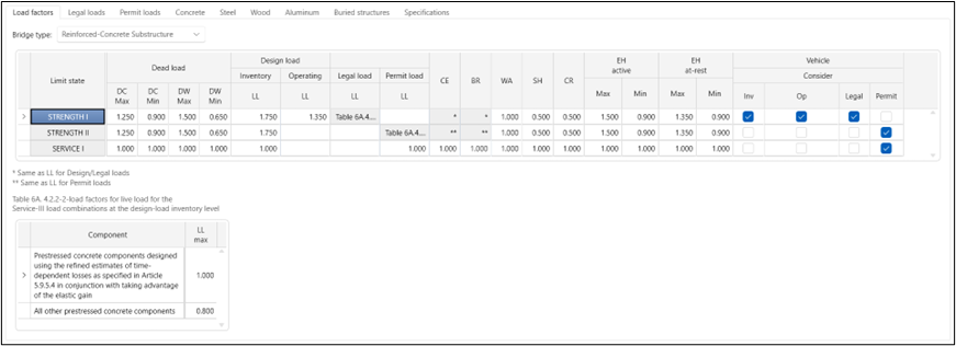
Loads
The substructure rating will consider all permanent loads and live loads, including vehicle braking, but will neglect other transient loads such as wind and temperature. The following load types are considered:
- Dead loads from structural and nonstructural components (DC)
- Dead loads from wearing surfaces and utilities (DW)
- Vehicular live load (LL)
- Vehicular braking force (BR)
- Water load and stream pressure (WA)
- Shrinkage force effects (SH)
- Creep force effects (CR)
- Horizontal earth pressure (EH)
A finite element model is generated for the complete pier alternative and analyzed for all superstructure and substructure loads. Element actions are collected for the pier cap components and specification checking calculations are evaluated for cross sections in the pier cap. Concurrent force effects are considered for rating when computing shear capacities. Design review articles processed in a load rating will continue to consider envelope forces.
For piers with drilled shaft foundations, the program will perform a nonlinear analysis to determine an equivalent linear model to compute dead load and live load actions for rating.
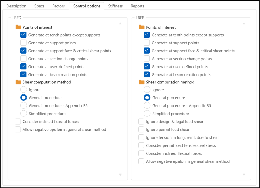
Control Options
New analysis control options are available for pier alternatives and introduce similar options as are available for superstructure member alternatives. Control options have been added for both LRFD and LRFR analysis methods. Points of interest options specify locations where specification checking is performed on the pier cap. The ‘Generate at beam reaction points’ is a new specification check location preference for pier caps which evaluates specification requirements at the bearing locations on the pier cap. The shear computation method option specifies which shear capacity calculation the program uses to compute beta and theta. In previous versions, the design review for piers always used the General procedure with Appendix B5.
The LRFR options include ‘Ignore tension in long. reinf. due to shear’ which determines whether the requirements from MBE 6A.5.8 – Evaluation for Shear will be considered and ‘Consider permit load tensile steel stress’ which determines whether the requirements from MBE 6A.5.4.2.2b – Permit Load Rating will be considered.
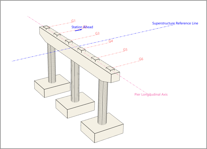
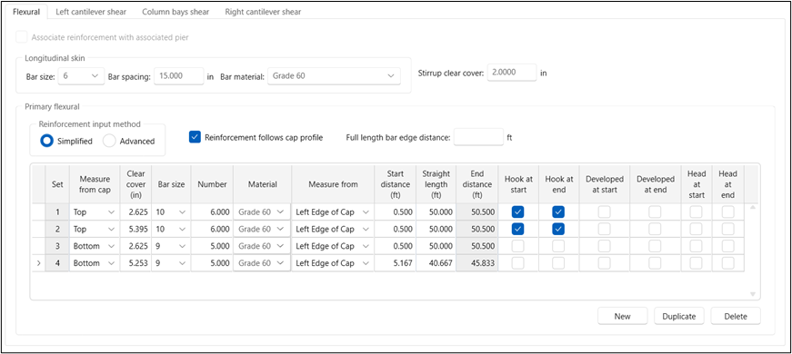
Reinforcement Definitions
Reinforcement input for pier alternatives is redesigned to more easily specify mild steel locations within the cap and columns. This includes options to define flexural reinforcing steel locations relative to the left edge of the cap, each column centerline, right edge of cap or along the full length. Shear reinforcement is defined within a given pier cap span or end cantilever and can be referenced from the edge of the cap, a column face, or a column centerline. Reinforcement input in existing BrD substructure models is migrated to the new input definitions.
Pier Association
Version 7.8 introduces a new concept of pier association. Users can define a control pier and associated piers. The control pier is a fully defined pier alternative with geometry, reinforcement, and loads. Associated piers are linked to a control pier to define certain geometric and reinforcement properties. The following list describes the pier association:
- The user fully defines a pier alternative (geometry, reinforcement, and loads) for a pier. This pier alternative is considered as the control pier alternative.
- For another pier within the same bridge alternative, the user creates a new pier alternative of the same type and associates this new pier alternative with the control pier. This pier alternative is considered the dependent pier alternative.
- The dependent pier alternative is populated with the geometry and reinforcement from the control pier alternative. Loads are not populated in the dependent pier alternative.
- The user can modify the elevation data in the dependent pier alternative but not the gross geometry such as the width and length of the cap, number of columns, or column shape.
- If the user changes a gross geometric property or reinforcement property in the control pier alternative, the corresponding property in the dependent pier alternative is updated as well.
- The user can override the reinforcement association to edit the reinforcement definition in the dependent pier alternative.
- Footing properties are populated in the dependent pier alternative; all dependent pier alternative footing properties can be modified.
Additional Features
The pier cap rating enhancement introduces many additional features to substructure piers.
The model generation settings allow for enhanced definition of element release at the top of columns. Element connectivity can be specified in both the pier longitudinal and pier transverse directions and is defined as fixed, free, or with an equivalent spring constant. These settings are considered when building the finite element model for both a design review and load rating.
The pier alternative definition includes enhanced user defined POIs for pier caps and columns. These new POI definitions more closely follow the POI definitions for a superstructure member and allow overrides for shear calculations, rebar development, shear capacities, positive flexural capacities, and negative flexural capacities. The new POIs are considered for both design review and load rating analysis methods.
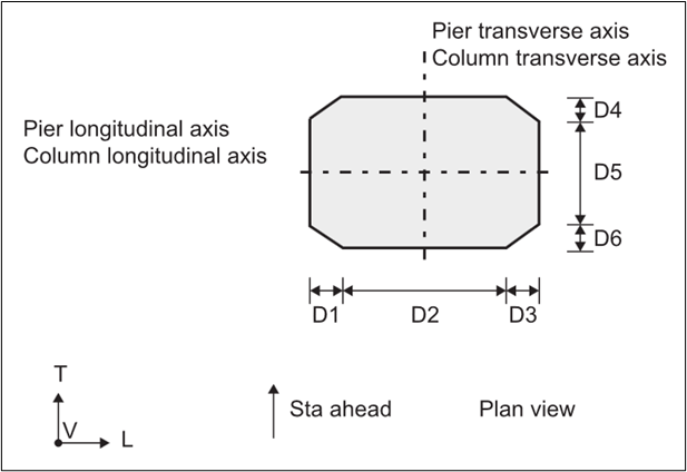
Hexagonal pier columns are supported. This geometry can be defined using the wedge nose column cross section type with a zero length D5 dimension. This shape is supported in both the design review and load rating analysis methods.
Users can define deterioration for pier caps and columns. This includes reductions to concrete area, flexural steel reinforcement, and shear steel reinforcement. The deterioration is considered in the specification checking calculations for a load rating only. Design review does not consider deterioration.